Contactors - The Building Blocks
The Building Blocks of Contactors
A contactor can stand on its own as a power control device, or as part of a starter. Contactors are used
in applications ranging from a light switch to the most complex, automated industrial equipment.
Contactors are used by electrical equipment that is frequently turned off and on (opening and closing the circuit),
such as lights, heaters and motors. The function of the contactor is always the same; to make and break all power
supply lines running to a Load or, as defined by NEMA, to repeatedly establish and interrupt an electrical power circuit.

Contactor Building Blocks
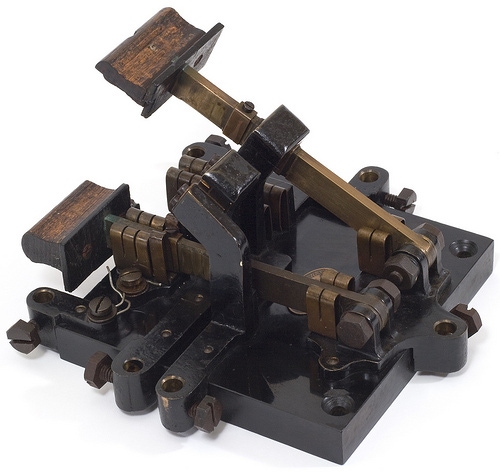
- Knife-Blade Switches - The first device used to stop and start electric motors was a simple Knife Blade Switch. This was a lever that would drop a strip of metal onto a Contact to make the electric circuit. In the late 1800's, "throwing the switch" meant that someone had to stand next to the knife blade switch and level it into the closed position. Engineers discovered that the contacts quickly wore out because humans could not open and close the switch fast enough to prevent arcing, which corroded the soft copper switches with pits, making them more susceptible to dirt and moisture. More importantly, as motors became larger, the currents to operate them also had to become larger, creating a serious safety concern. It was physically dangerous to handle the switch. Mechanical improvements were made, but with their dangerous operation and short contact life, knife blade switches remained at a design dead-end.
- Manual - The manual controller was the next stop up the evolutionary ladder, offering several important new features:
- The unit is encased, not exposed
- Double-break contacts are used instead of single-break
- The unit is physically smaller
- The unit is much safer to operate
Double-break contacts open the circuit in two places simultaneously. Dividing the connection over two sets of contacts allows you to work with more current in a smaller space than available with a single-break contact. In addition, the mechanical linkage consistently opens and closes the circuit, sparing the metal from some of the arcing experienced under knife blade switches.With a manual controller, the operator presses a button or moves a switch that is integral to the electrical equipment being run. In other words, the button or switch is physically attached to the controller itself, and is not operated remotely. When an operator activates a manual controller, the Power Circuit engages, carrying the electricity to the load. - Magnetic Contactors - Engineers eventually made a breakthrough with the magnetic contactor. A magnetic contactor is operated electromechanically without manual intervention. This means that the contactor can be operated remotely, without the need for putting a person in a potentially dangerous location. Magnetic contactors use a small control current to open and close the circuit.
Types of Contactors
There are different classifications of contactors used for many different applications. Two of the main classifications for motor control components are the International Electrotechnical Commission (IEC) and the National Electrical Manufacturers' Association (NEMA). The differences between the IEC and NEMA classified components is reflective of their size, speed, functionality and power. IEC and NEMA also rate their components based on different philosophies. North American (NEMA) general purpose machine tool contactors generally emphasizing simplicity of application while definite purpose and European rating (IEC) philosophy emphasizes design for the intended life cycle of the application. Over all, contactors are split between these two classifications. Some examples include:
- AC Mechanically Interlocked - IEC
- DC Mechanically Interlocked - IEC
- AC Reversing - IEC
- AC Non-Reversing - IEC
- AC Reversing - NEMA
- AC Non-Reversing - NEMA
Another popular type of contactor is a Definite Purpose Contactor . Definite Purpose Contactors are electrically operated switching devices specifically designed for the heating, ventilation, air conditioning and refrigeration (HVAC) industry. They are controlled by automatic thermostat control or manual pushbutton interfaces.
 Mechanically interlocked contactors, like the ones pictured above, are designed for reversing 2 speed, reduced
voltage, type starter applications.
Mechanically interlocked contactors, like the ones pictured above, are designed for reversing 2 speed, reduced
voltage, type starter applications.How Contactors Operate
- Movable contacts
- Stationary contacts
- Armature
- Spring
- Coil
- E-Frame
Contactor Applications
Some major applications of contactors include lighting circuits, heaters and transformers. Contactors are often used to provide central control of large lighting installations, such as an office building or retail building. To reduce power consumption in the contactor coils, latching contactors are used, which have two operating coils. One coil, momentarily energized, closes the power circuit contacts, which are then mechanically held closed; the second coil opens the contacts.
Magnetic starters include a contactor as an essential component, while also providing power-cutoff, under-voltage, and overload protection. Electromagnetic contactors are actuated by electromechanical means. They make and break power circuits to such loads as electric furnaces, lights, transformers, capacitors, heaters and, when overload relays or inherent protectors are used, motors. Pushbuttons and selector switches, like the ones on a control panel, are used in hundreds of manufacturing industries. Each button and switch is connected to a contactor for use in making or breaking an electrical circuit remotely. They are used in applications such as elevators, pools, food processing, pumps/compressors, lighting, hoists and cranes, battery chargers, printing presses, vending machines, and agricultural processes.
Life Expectancy of Contactors
The major customer concern is the life expectancy of a contactor. The more frequently the contacts are opened and closed, the shorter the life of the contactor. As contacts open and close, an electrical arc is created between them. The arcs produce additional heat, which, if continued, can damage the contact surfaces. The faster the contact closes, the sooner the arc is extinguished, and the longer the life expectancy of the contact. There is, however, an issue with modern contactors that have been designed to close so quickly and with such energy that the contacts slam against each other and rebound, causing a bouncing action. This bouncing action is referred to as Contact Bounce and when the contact bounces away, a secondary arc is created. The contacts slam together again and again, each time the bouncing and arcing become less and less. In addition to closing the contacts as fast as possible, it is desirable for the contacts to bounce as little as possible to reduce secondary arcing and wear.
 Electrical arcing is a key contributor to the shelf-life of a contactor. The arc between the contacts creates additional heat which, in time, can damage the contact surfaces.
What is a Contactor?